
USB-C PD Multi-Rail PSU Drop-In Replacement for Atari ST/STE/MegaST
This USB-C PD multi-rail DC-DC power supply kit (+5 V, +12 V, −12 V) is a drop-in replacement for the original Atari ST/STE/MegaST PSU. After 30+ years, many stock units can fail, act unpredictably, or even threaten the computer. This kit provides a safe, efficient, and reliable upgrade that will keep your machine running for years, with the added convenience of using a modern USB-C PD power adapter.
What’s in the Box
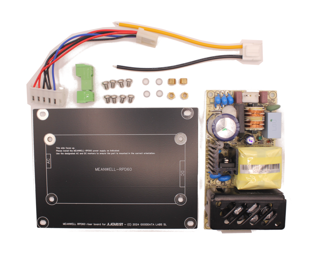
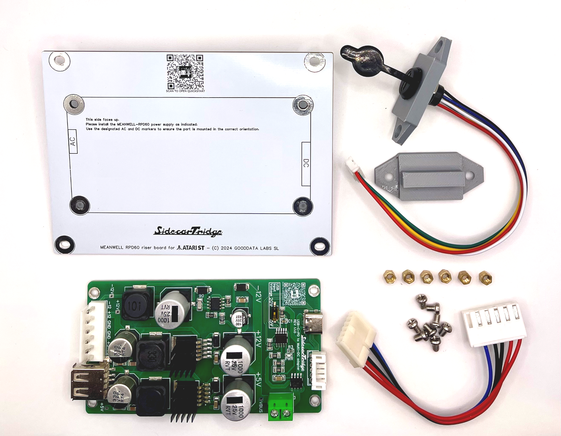
The USB-C PD Multi-Rail PSU Drop-In Replacement Kit for Atari ST/STE/MegaST includes:
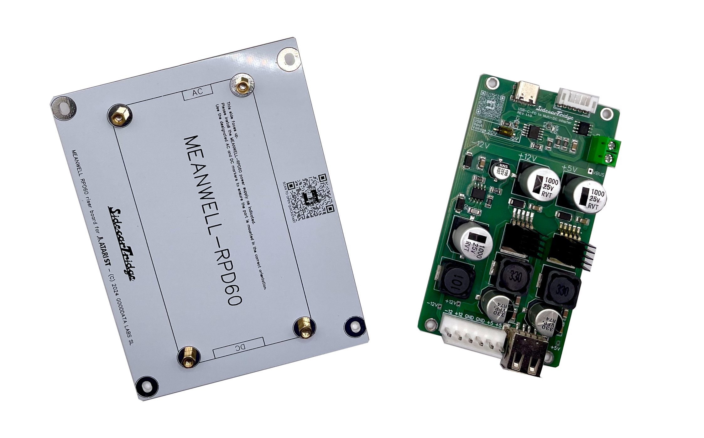
- Riser PSU PCB for the USB-C PD Multi-Rail board, sized to the original PSU mounting points. It shares the mechanical layout with the Solderless PSU Kit that uses the Mean Well RPD-60A AC/DC supply.
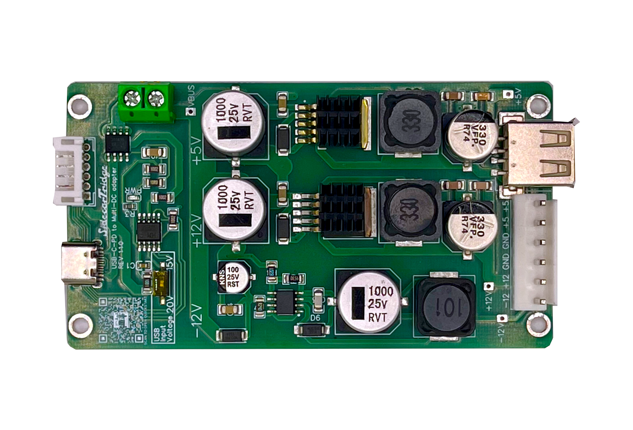
- SidecarTridge USB-C PD Multi-Rail power board.
- 8 × M3 × 4 mm Phillips screws.
- 6 × M3 nuts.
- JST-VH 3.96 mm 6-pin female to TE-171822-6 6-pin female harness, 10 cm.
- 3D-printed replacement cover for the original AC inlet with a USB-C PD receptacle and JST-PH 2.0 terminated cable.
- 3D-printed replacement cover for the original PSU switch.
Note that tools for installation are not included. A Philips screwdriver, a small flat screwdriver, and a cutter/scissors/tool for stripping wires will be required.
Step 0: Checking Compatibility
The USB-C PD Multi-Rail PSU Drop-In Replacement Kit is compatible with the following models:
- Atari STF
- Atari STFM
- Atari MegaST
- Atari STE
Step 1: Unboxing the Kit
Unbox the kit and confirm that all components are present and undamaged. Any missing or defective items should be reported via the contact page.
Step 2: Removing the Original PSU
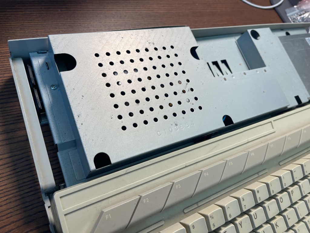
Ensure the computer is turned off and disconnected from the power supply before proceeding. Open the computer case by removing the screws holding it together and sliding off the cover. The exact process may vary depending on the model. Locate the original PSU near the power switch.
Remove the screws holding the PSU cage.
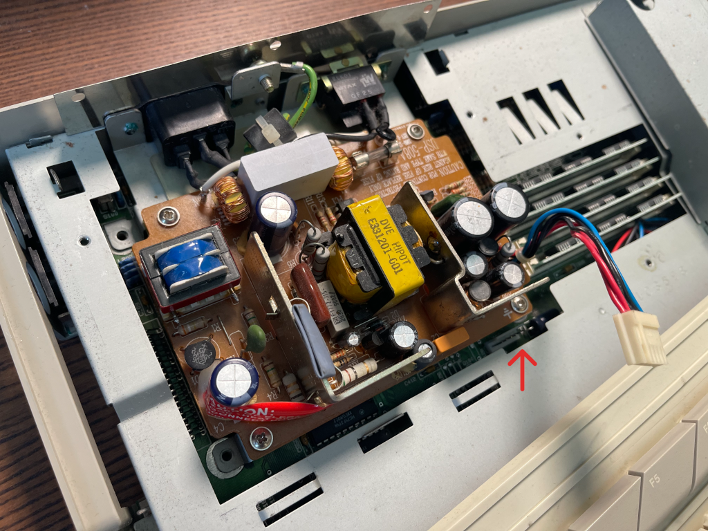
Unplug the PSU from the motherboard. The connector typically has six wires: 2 red (5V), 1 blue (12V), and 3 black (ground). Pull the connector gently from the motherboard.
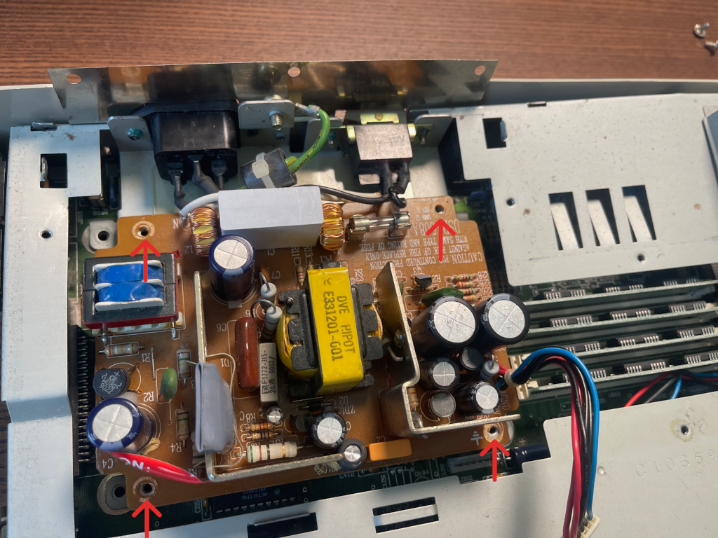
Remove the screws securing the old PSU to the metal holder and keep them. Do not remove the PSU from the holder just yet.
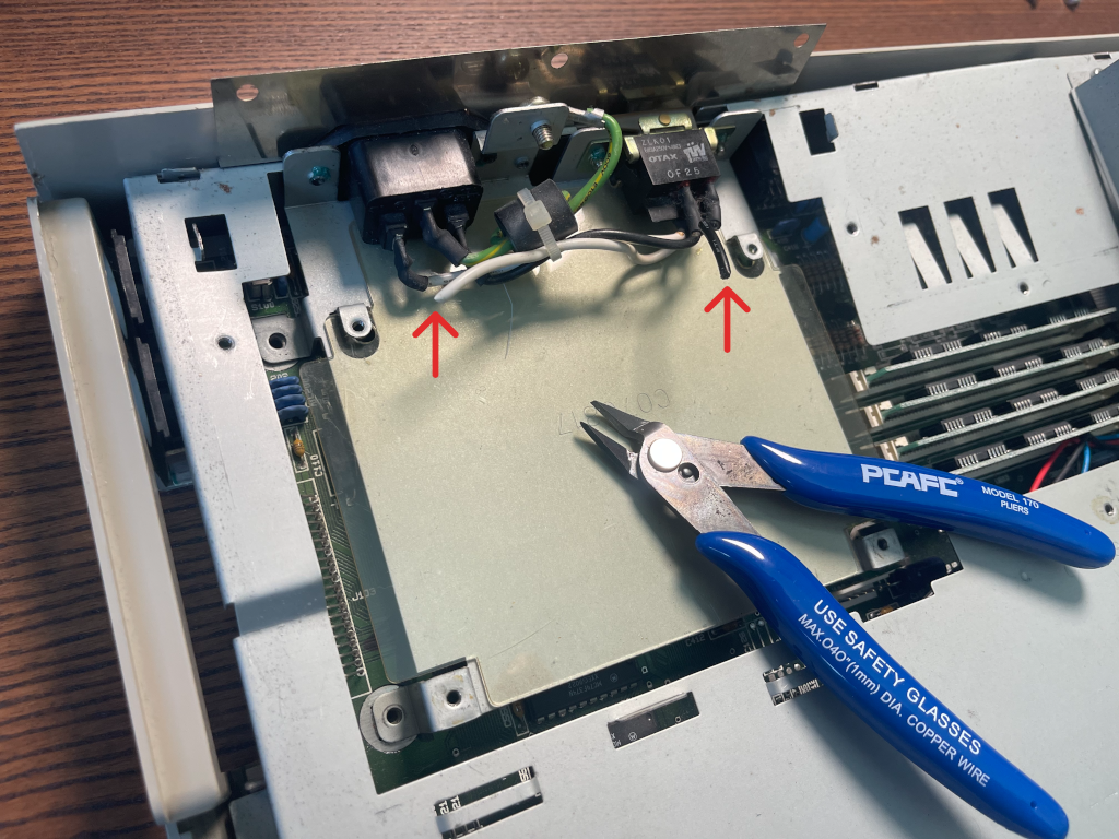
Cut the soldered wires connecting the AC cable to the PSU, leaving enough wire if you want to reuse the original rocker switch.
Step 3: Assembling the New PSU on the Riser PCB
Secure the PSU to the Riser PCB using the included screws and nuts. Start by placing the Riser PCB on a flat surface with the rear side facing up. Insert four screws through the holes, securing them with the nuts.
Flip the PCB to face forward, exposing the opposite side of the holes. It should look like this:
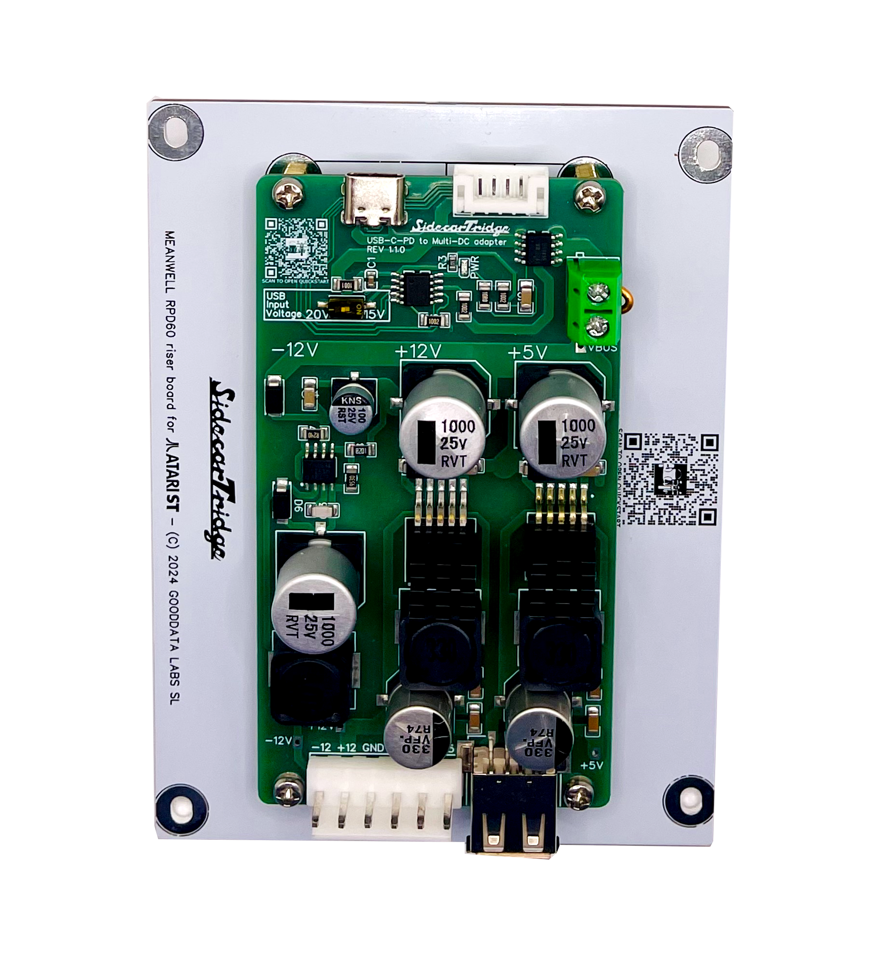
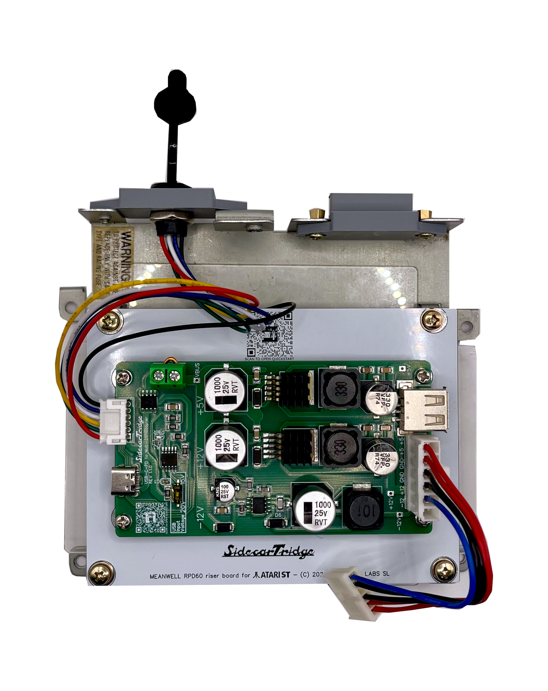
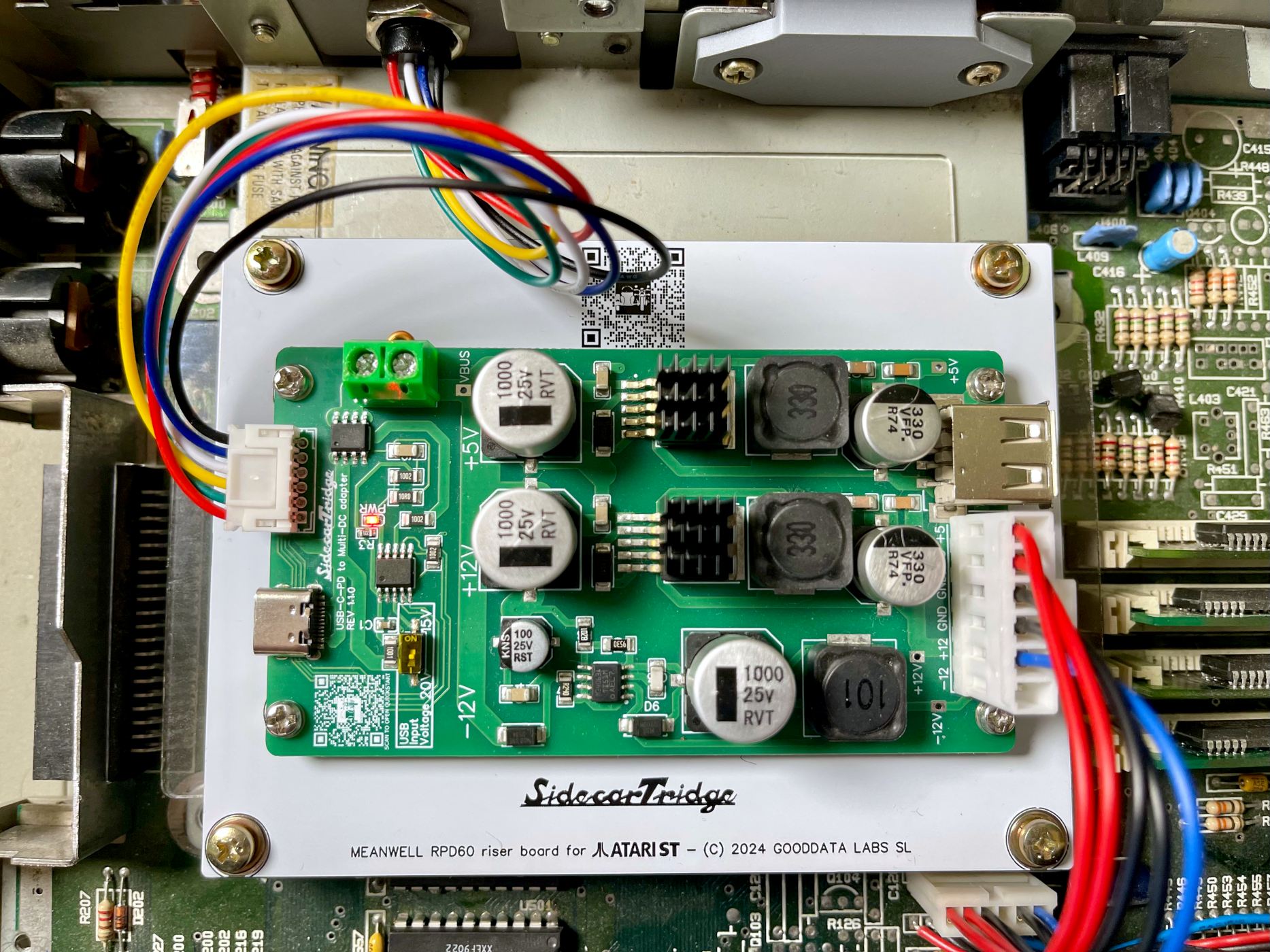
Place the USB-C PD board on the Riser PCB, aligning the screw holes with the nuts. It should appear like this:
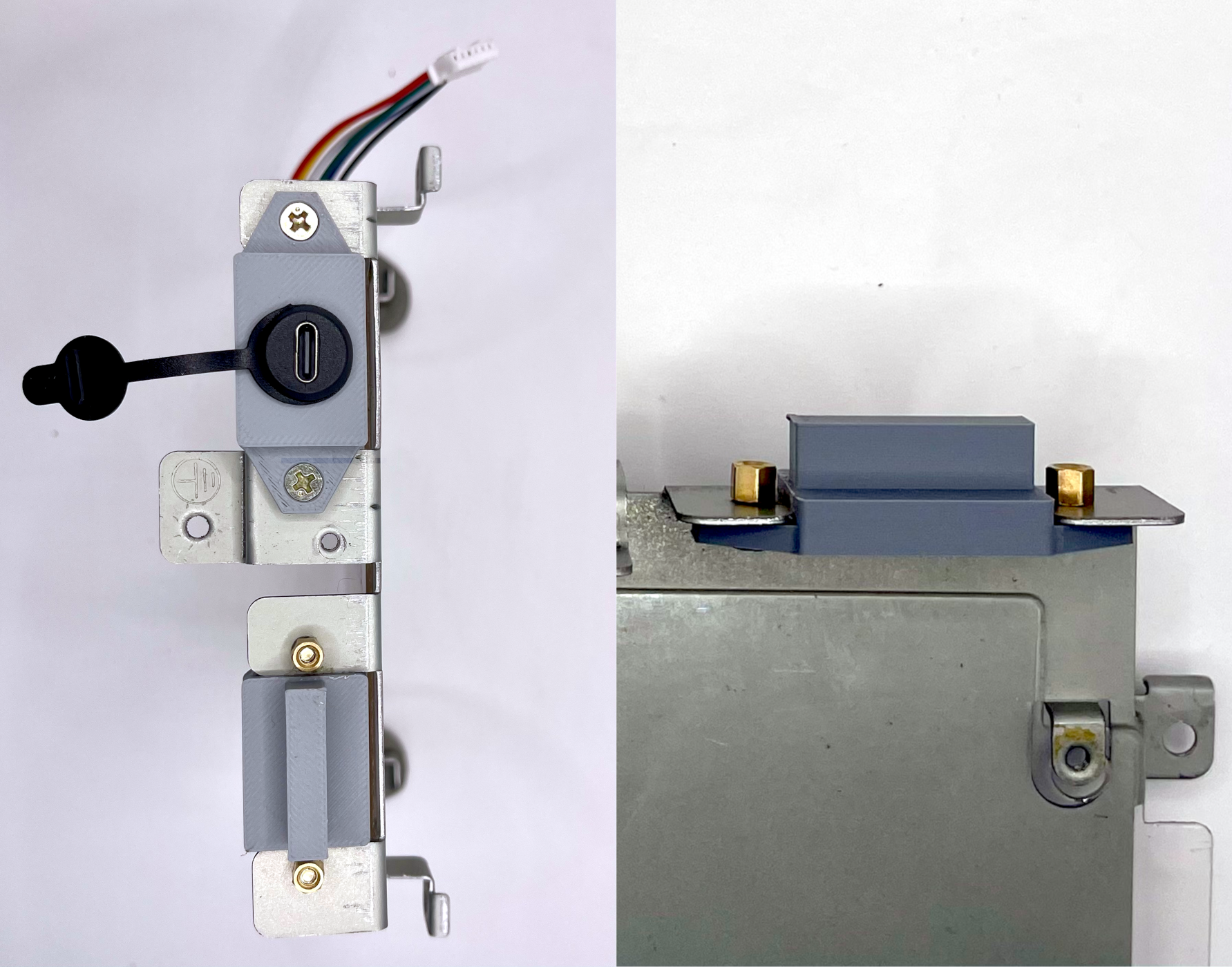
Insert the 3D-printed USB-C PD inlet cover into the original AC inlet slot. Secure it with the original screws.
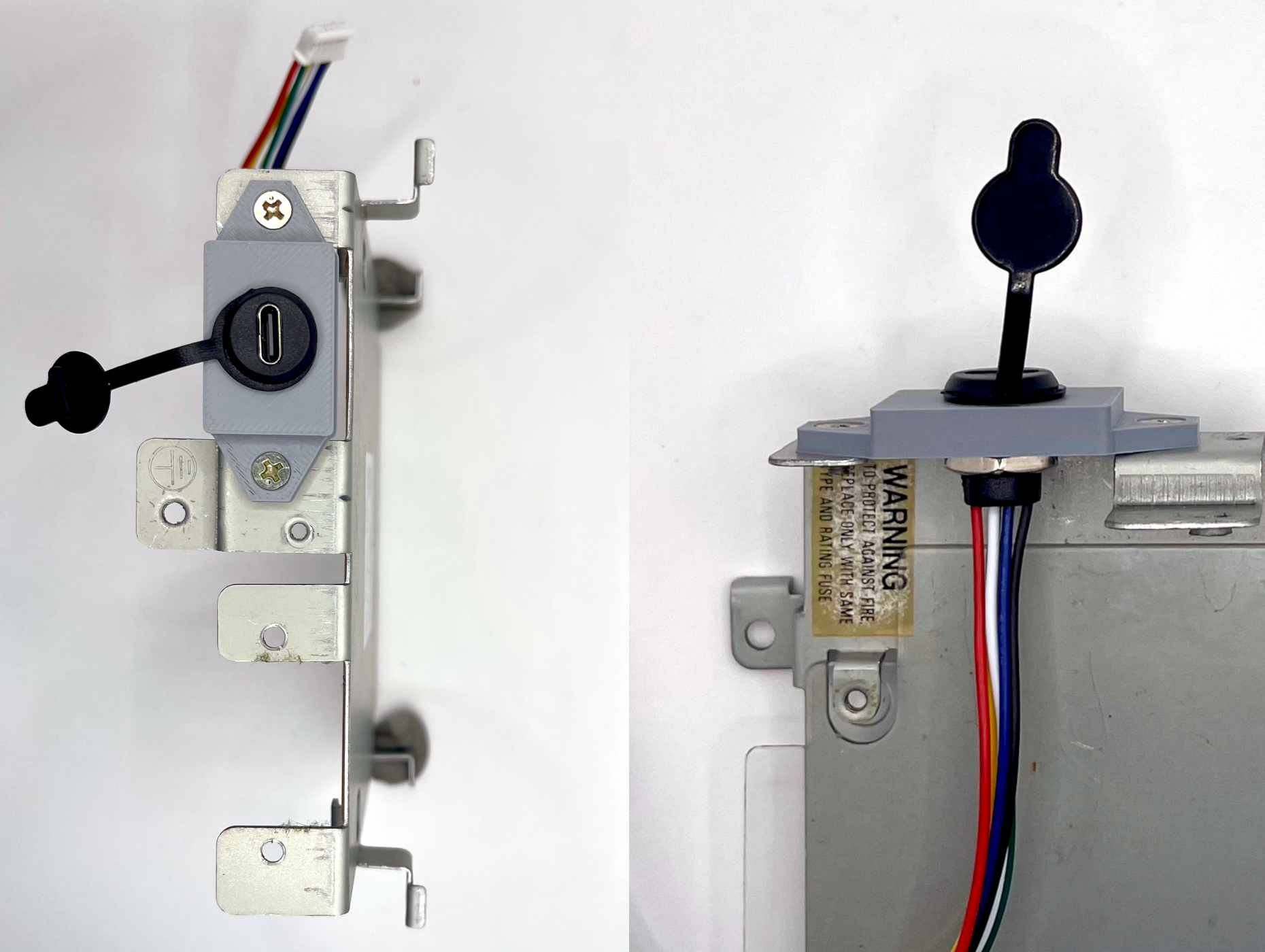
Next, insert the 3D-printed switch cover into the original switch slot. Secure it with the original screws and two M3 nuts included in the kit.
Then, connect the JST-PH 2.0 connector to the USB-C PD board connector, and the JST VH 3.96 mm 6-pin connector. In the Atari ST PSU wiring, both the JST VH3.96 and TE-171822-6 connectors use only 5 of their 6 positions. The unused pin is a ground, and since multiple grounds are already provided, 5 connections are enough for proper operation.
Finally, place the new PSU in the metal holder, ensuring a plastic insulator is between the PSU and the holder. If missing, electrical tape can be used as insulation.
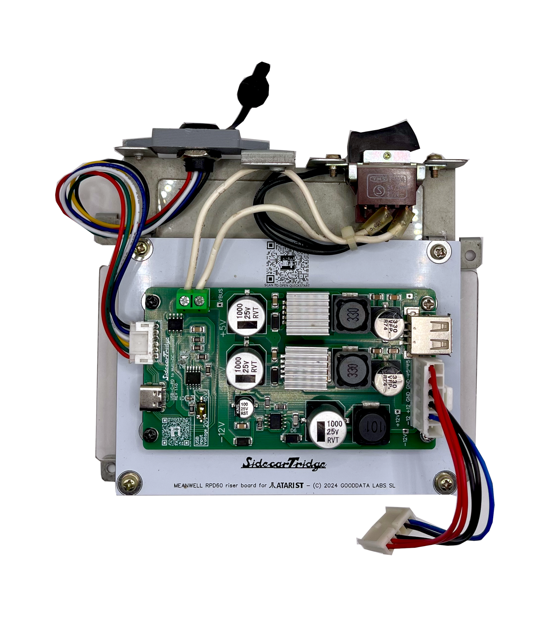
Step 4 (Optional): Reusing the Original Rocker Switch
If you want to reuse the original rocker switch follow these steps:
- Strip about 2mm of insulation from the cable wires connected to the original rocker switch using a cutter, scissors, or other suitable tool.
- The rocker switch has four cable wires: two black and two white. We only need to connect the black or white pair. The other pair can be insulated with electrical tape.
- Connect the black or white pair to the two-pin green terminal block on the USB-C PD board. It does not matter which wire goes to which terminal, just ensure a secure connection. Keep the copper jumper that was installed in the terminal block in a safe place in case you don’t want to reuse the original switch in the future.
Adjust the PSU riser board’s position so the screw holes align with those in the metal holder, then secure using the screws from the old PSU.
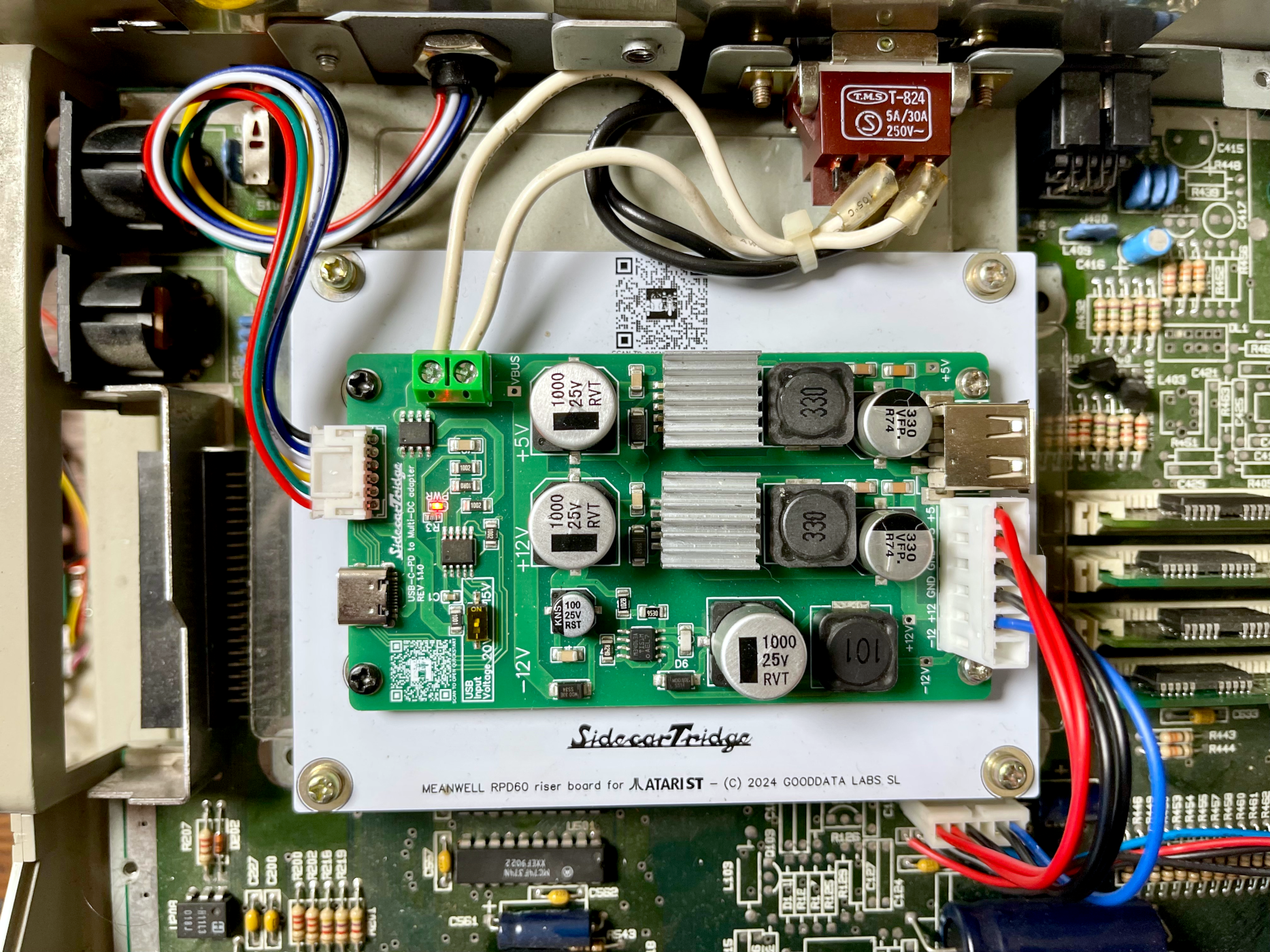
Step 5: Installing the New PSU
Place the new PSU assembly into the computer, aligning the screw holes with those in the metal holder. Secure it using the screws from the old PSU. Try not to overtighten the screws
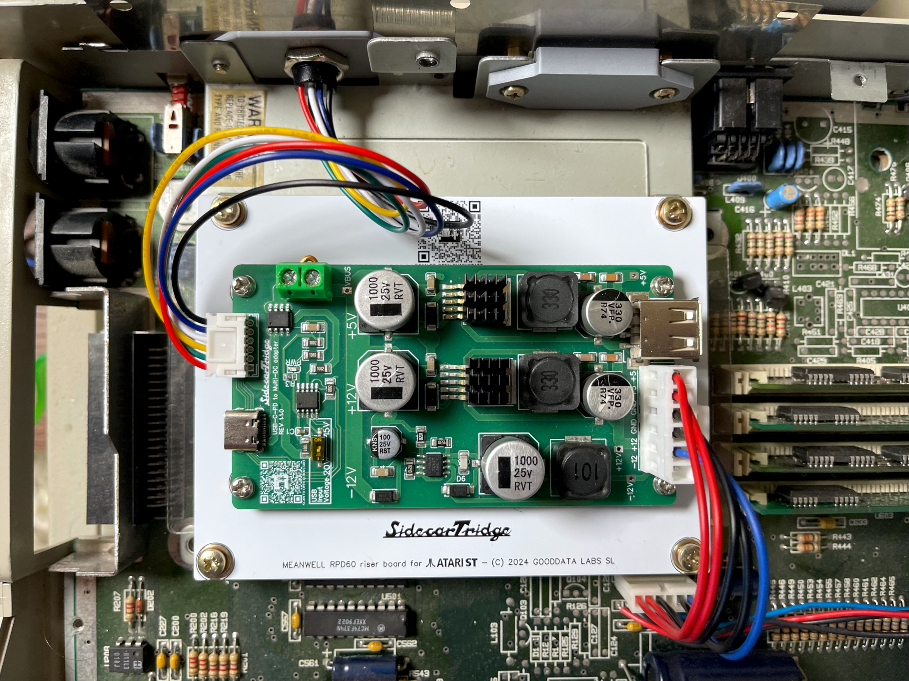
If you reused the original rocker switch, ensure all cables are securely connected and insulated with electrical tape to prevent short circuits.
Step 6: Testing the New PSU
To test the new PSU, connect a USB-C PD power adapter to the USB-C inlet. Please be aware that the minimum power requirement for the USB-C PD power adapter is 60W (20V/3A, 15V/4A). Please read the documentation site for a recommended list of USB-C PD power adapters.
Most of the USB-C PD power adapters used to charge laptops will work fine. If the power adapter does not provide enough power, the computer may not boot or may behave unpredictably.
By default, the USB-C PD board is configured to request 20V from the power adapter. It is also possible to configure it to request 15V by changing the position of the small switch on the board:
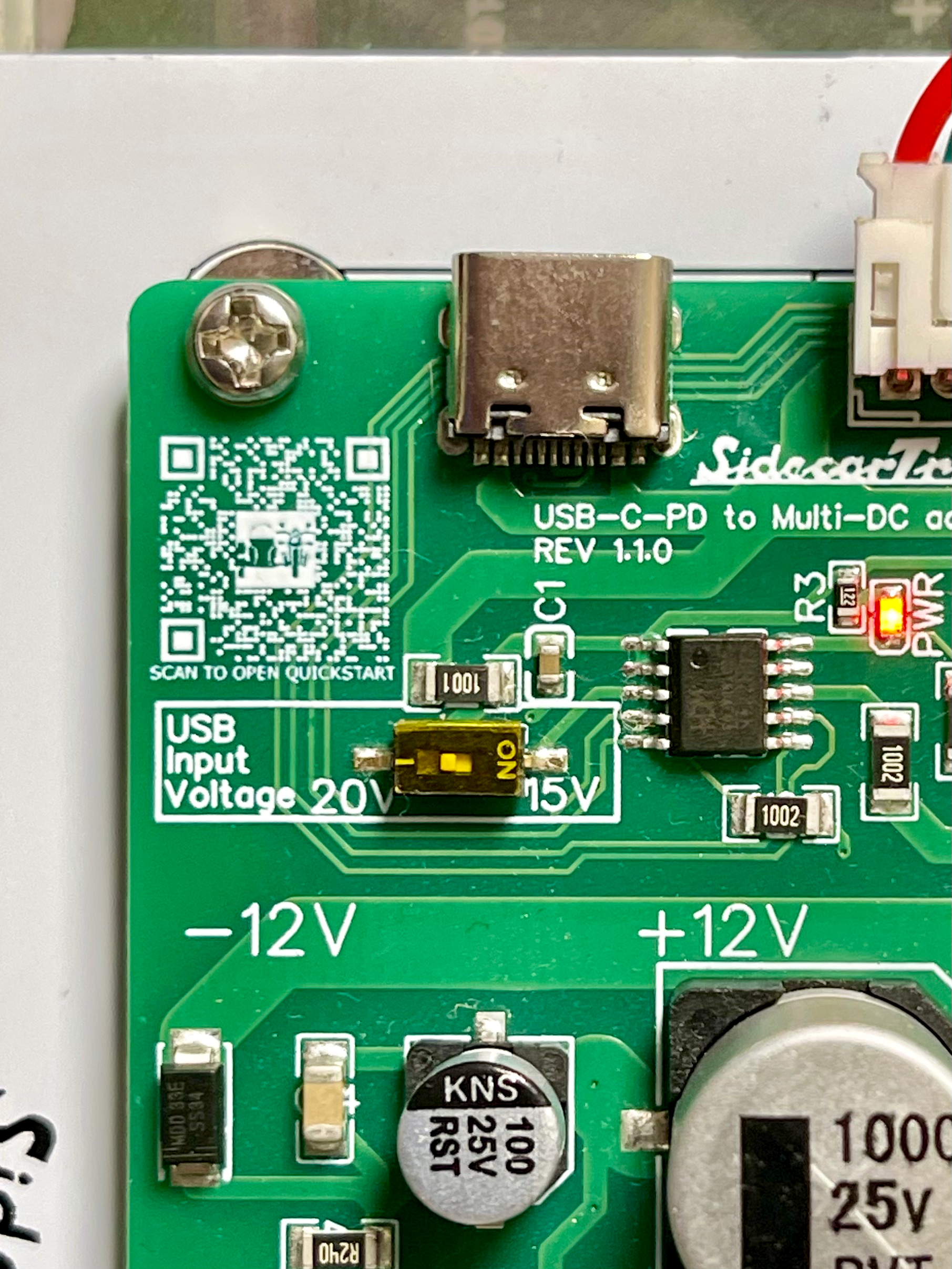
We recommend keeping the switch in the 20V position unless you have a specific reason to change it.
When the power adapter is connected and the switch is turned on, the red LED on the USB-C PD board should light up, indicating that the board is receiving power and it could successfully negotiated the power contract with the power adapter. If the LED does not light up, disconnect the power adapter and verify that your power adapter is capable of delivering at least 60W at 15V or 20V.
If the tests were successful, connect the DC cable to the motherboard using the six-pin TE connector.
The most common problem
If your computer restarts and the power LED blinks, it is likely that your USB-C PD power adapter is not providing enough power. Please try a different USB-C PD power adapter that can deliver at least 60W (20V/3A, 15V/4A). The Atari ST and Mega ST can work safely with a power supply of less than 60W, but the Atari STE requires a minimum of 60W to operate correctly. Sadly, many USB-C PD power adapters do not provide the advertised power, so it is essential to use a reliable and tested power adapter.
Conclusion
After successfully installing the USB-C PD PSU Kit for Atari ST, the Atari ST/STE/MegaST should now run smoothly. For further assistance or questions, contact us via the contact page. Enjoy!