The Solderless PSU Kit for Atari ST Solution
The Solderless PSU Kit for Atari ST offers a reliable and efficient replacement for the original power supply unit (PSU) of the Atari ST/STE/MegaST. With over 30 years in use, original PSUs are prone to failure, unpredictable behavior, or even computer damage. This kit provides a safe and reliable alternative to ensure continued functionality for many years to come.
What’s in the Box?
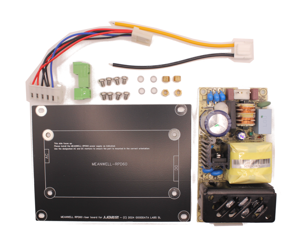
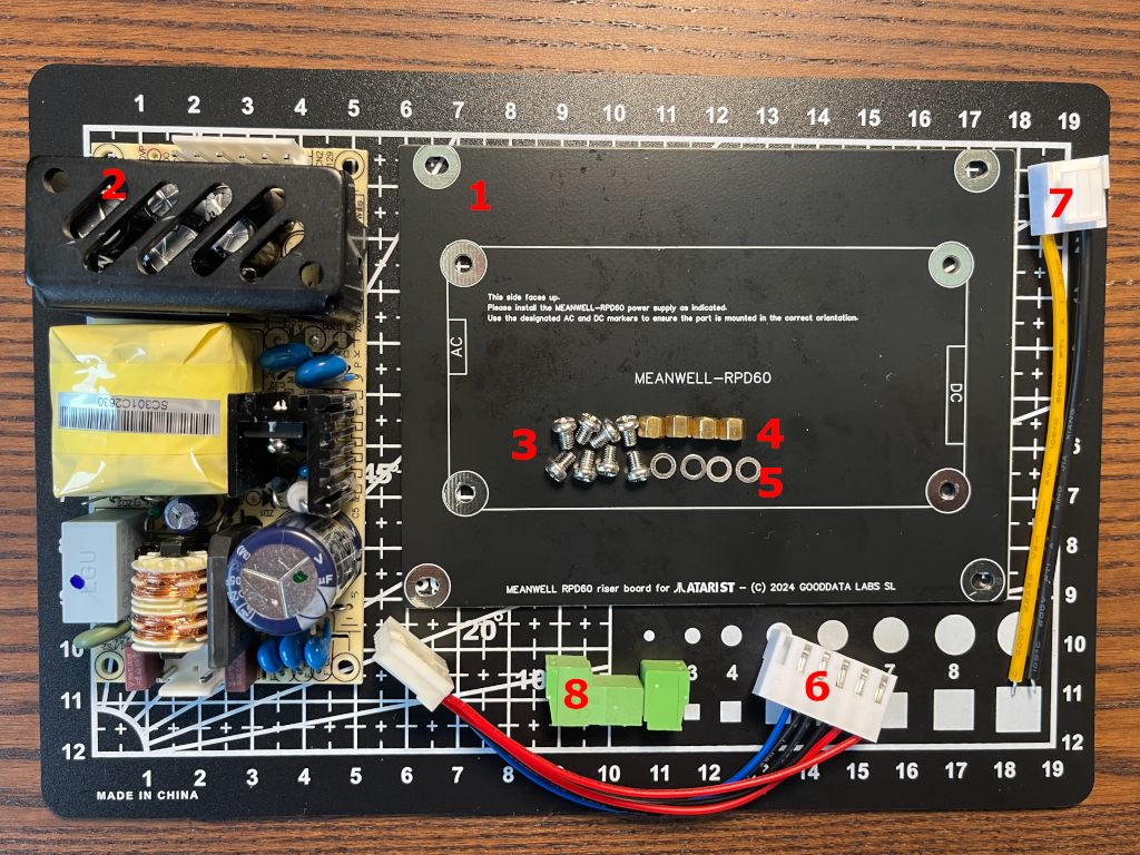
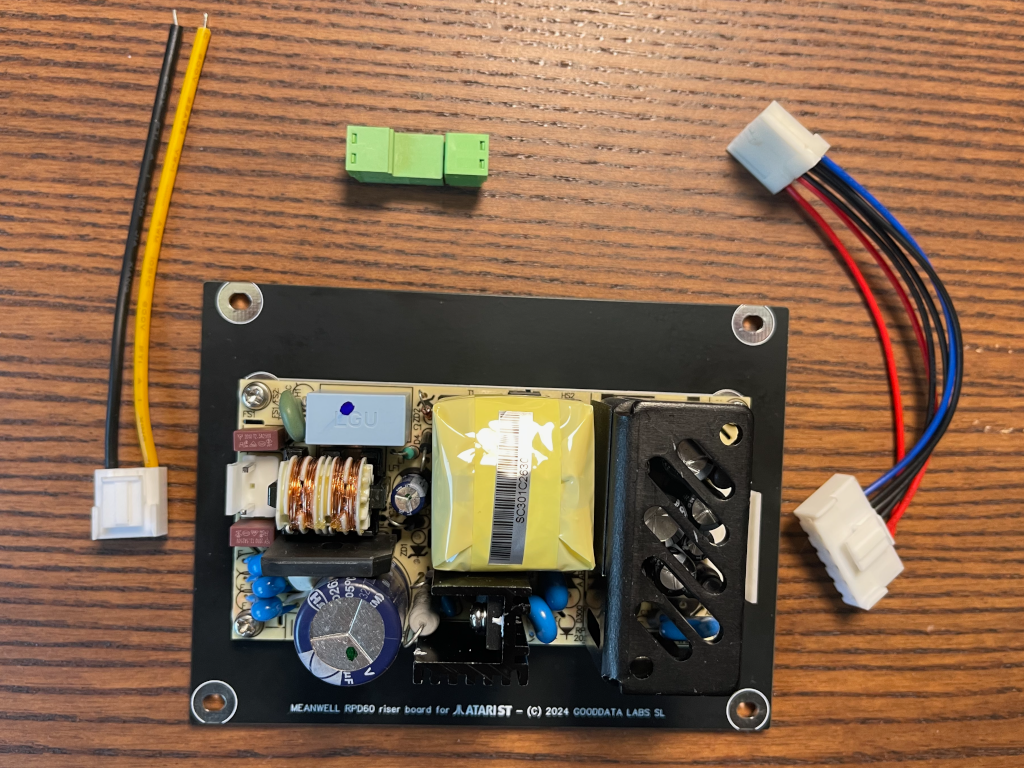
The Solderless PSU Kit for Atari ST includes the following components:
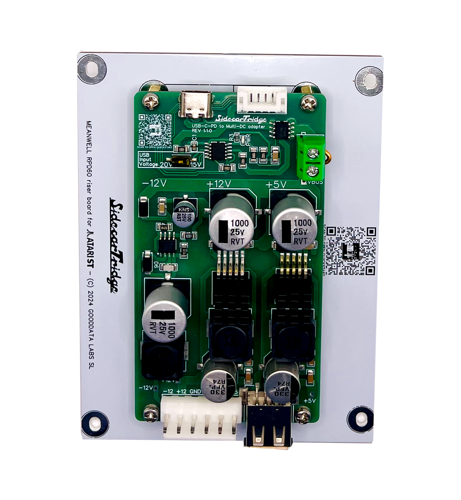
- 1x Riser PSU PCB for the Mean Well RPD-60A PSU
- 1x Mean Well RPD-60A PSU
- 8x Philips M3 4mm screws
- 4x M3 4mm nuts
- 4x M3 0.5mm washers
- 1x JST VH3.96 6-pin female connector to 6-pin TE-171822-6 female connector (10cm)
- 1x JST VH3.96 3-pin female connector (with 2 pins connected, 10cm)
- 1x 2-pin speak-on terminal block
Note that tools for installation are not included. A Philips screwdriver, a small flat screwdriver, and a cutter/scissors/tool for stripping wires will be required.
Step 0: Checking Compatibility
The Solderless PSU Kit is compatible with the following models:
- Atari STF
- Atari STFM
- Atari MegaST
- Atari STE
Step 1: Unboxing the Kit
Unbox the kit and confirm that all components are present and undamaged. Any missing or defective items should be reported via the contact page.
Step 2: Assembling the New PSU on the Riser PCB
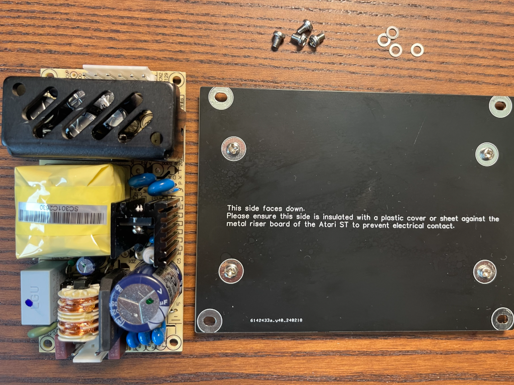
Secure the PSU to the Riser PCB using the included screws, nuts, and washers. Start by placing the Riser PCB on a flat surface with the rear side facing up. Insert four screws through the holes, securing them with the nuts. The assembly should resemble this:
Flip the PCB to face forward, exposing the opposite side of the holes. It should look like this:
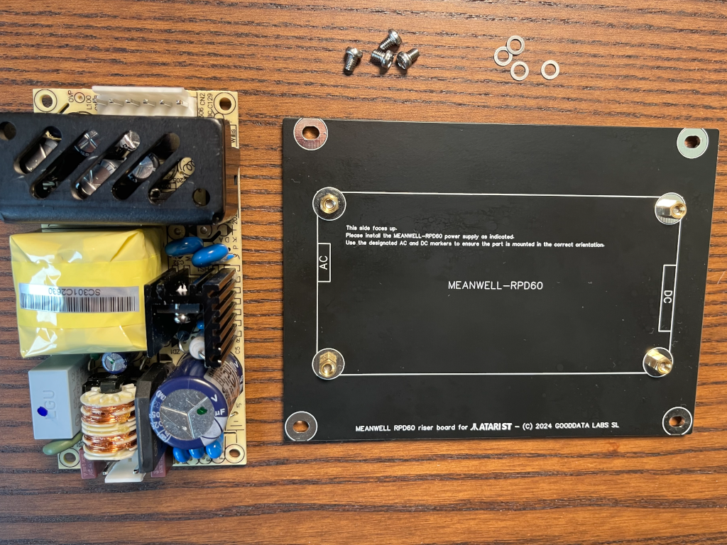
Place the Mean Well RPD-60A PSU on the Riser PCB, aligning the screw holes with the nuts. It should appear like this:
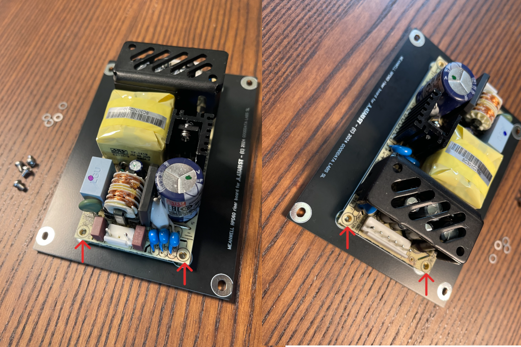
Attach the remaining four screws through the PSU’s screw holes and the nuts on the Riser PCB. Be sure to use washers between the screws and the PSU. It should resemble this:
Step 3: Removing the Original PSU
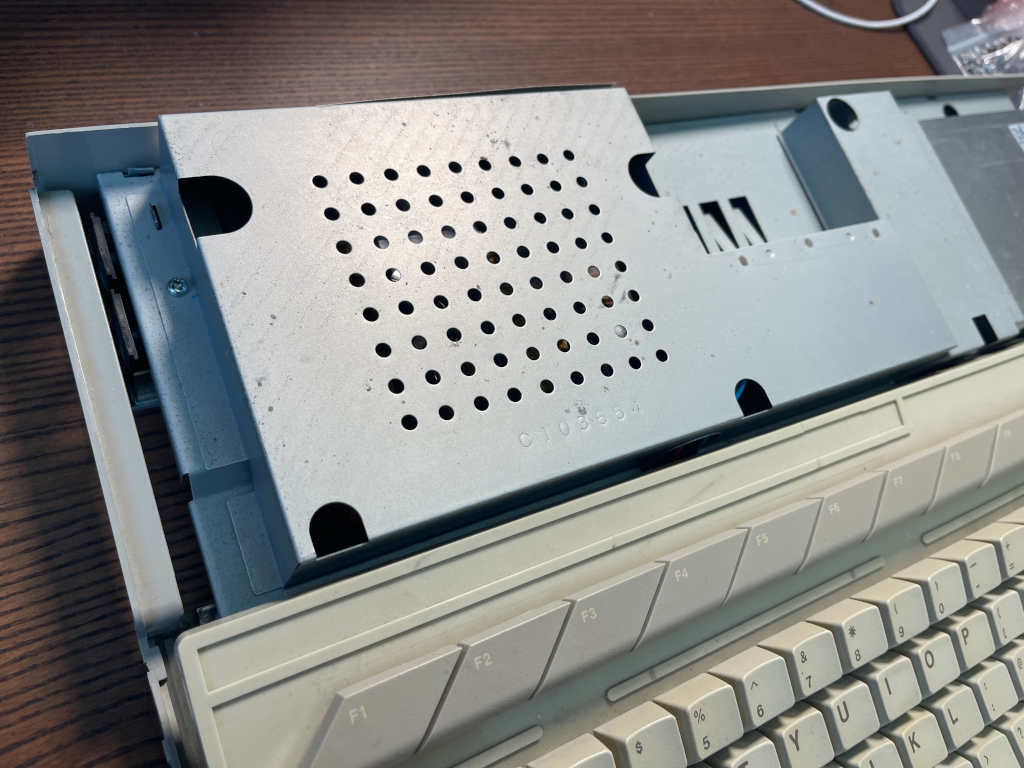
Ensure the computer is turned off and disconnected from the power supply before proceeding. Open the computer case by removing the screws holding it together and sliding off the cover. The exact process may vary depending on the model. Locate the original PSU near the power switch.
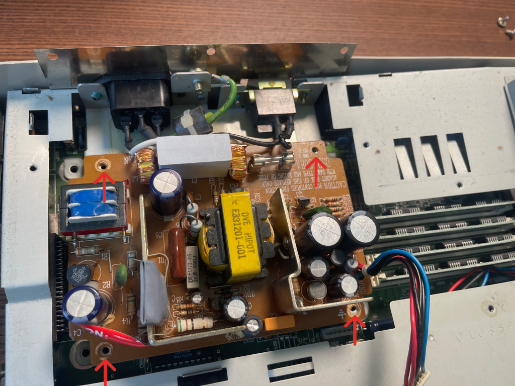
Remove the screws holding the PSU cage.
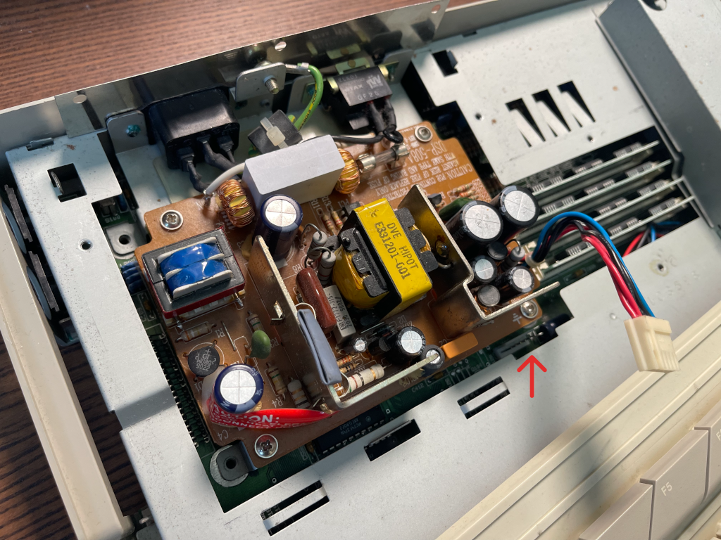
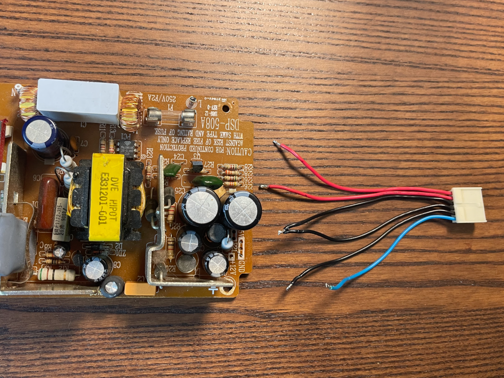
Unplug the PSU from the motherboard. The connector typically has six wires: 2 red (5V), 1 blue (12V), and 3 black (ground). Pull the connector gently from the motherboard.
Remove the screws securing the old PSU to the metal holder and keep them. Do not remove the PSU from the holder just yet.
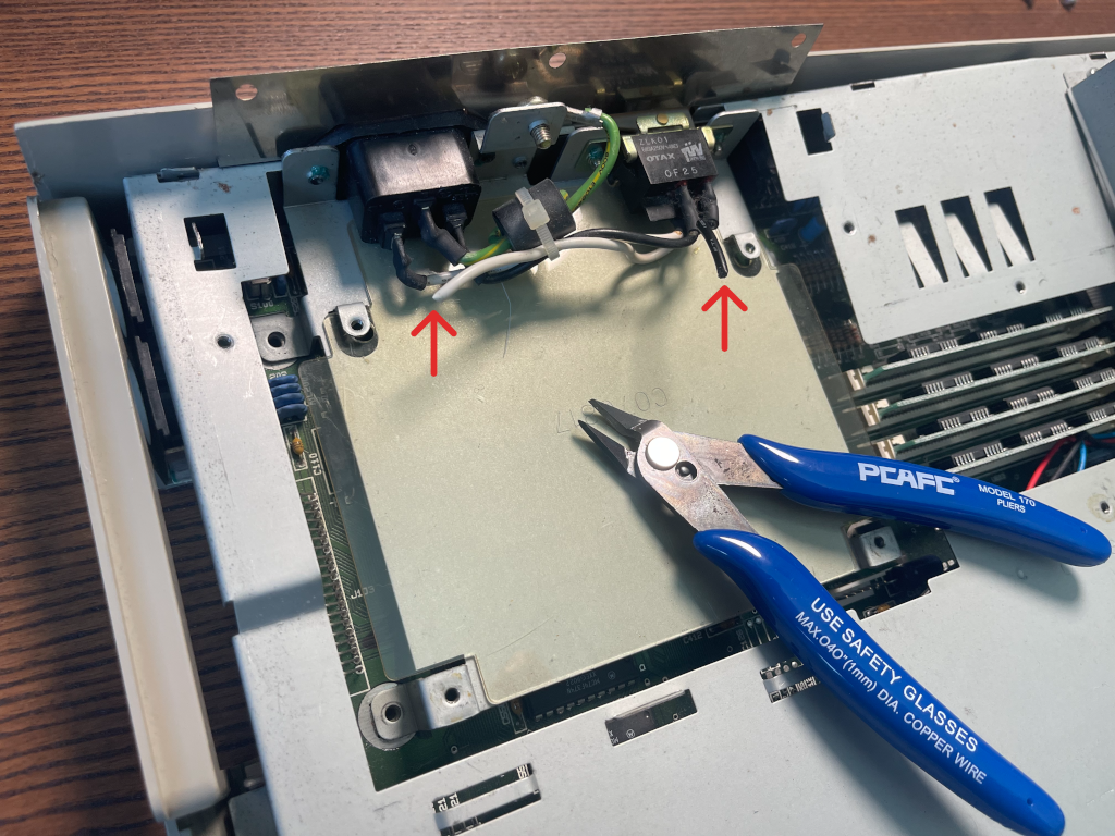
Cut the soldered wires connecting the AC cable to the PSU, leaving enough wire for reconnecting to the new PSU. The black wire is live, and the white is neutral.
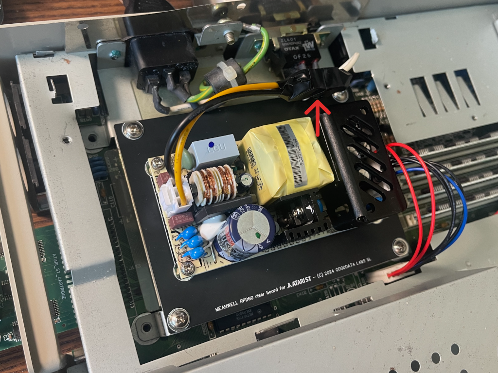
Step 4: Installing the New PSU
Strip about 2mm of insulation from the AC cable wires using a cutter, scissors, or other suitable tool. Place the new PSU in the metal holder, ensuring a plastic insulator is between the PSU and the holder. If missing, electrical tape can be used as insulation.
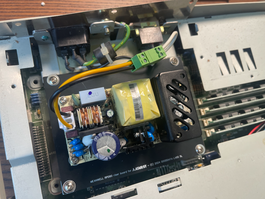
Adjust the PSU riser board’s position so the screw holes align with those in the metal holder, then secure using the screws from the old PSU.
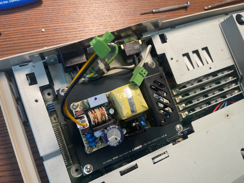
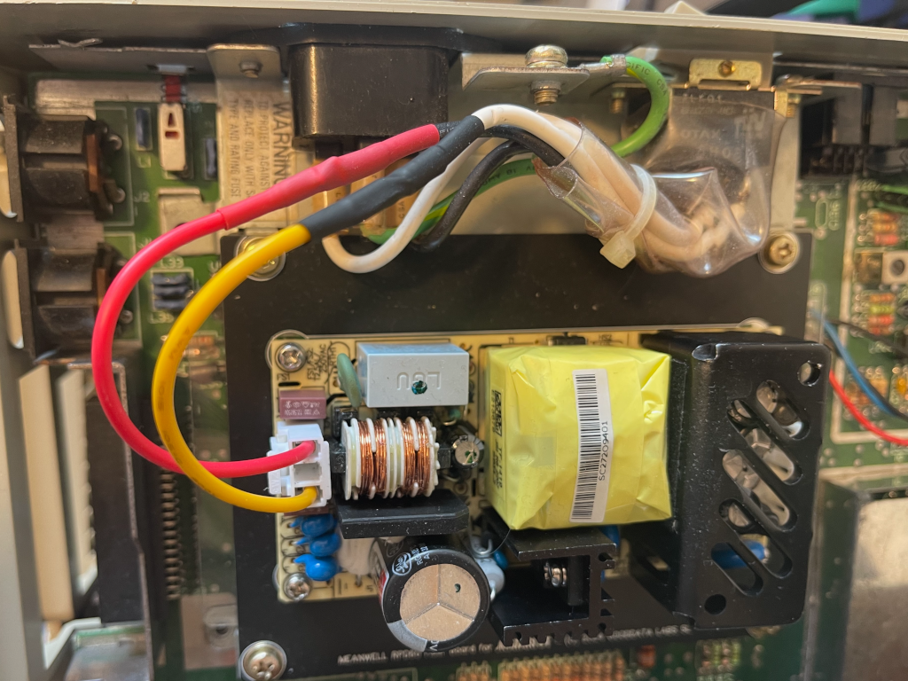
Connect the two-pin terminal block to the AC cable, noting that the PSU side uses yellow (neutral) and black (live). Secure the connections, then repeat for the switch cable.
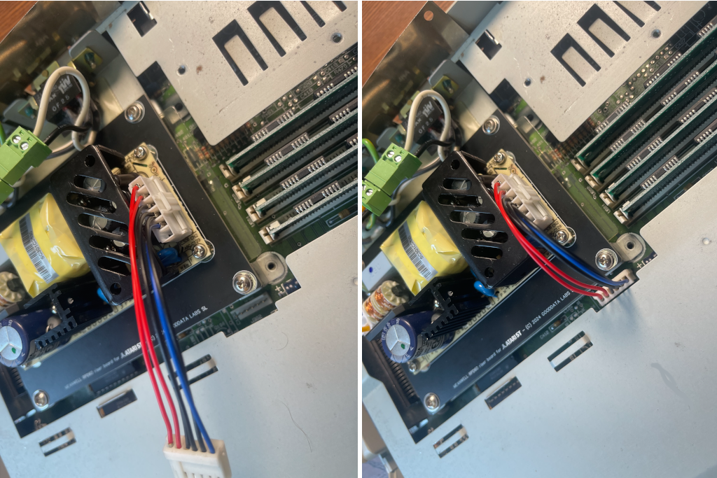
Connect the DC cable to the motherboard using the six-pin TE connector and the six-pin JST connector to the PSU. In the Atari ST PSU wiring, both the JST VH3.96 and TE-171822-6 connectors use only 5 of their 6 positions. The unused pin is a ground, and since multiple grounds are already provided, 5 connections are enough for proper operation.
Step 5: Testing the New PSU
Test the new PSU before closing the computer case by plugging it into a power outlet and turning it on. If the PSU is working correctly, the computer’s green power light will illuminate, and the screen and floppy drive LED will turn on. If it does not power up, verify that all connections are properly seated.
Securely route all cables and insulate the connections with electrical tape to prevent short circuits.
One More Thing…
This guide is a step-by-step tutorial for installing the Solderless PSU Kit for Atari ST, but users with basic soldering skills can improve the connection by soldering the AC cable directly to the PSU. This will prevent the cable from coming loose.
Another useful improvement is reusing the old PSU’s six-pin connector for future use.
Conclusion
After successfully installing the Solderless PSU Kit for Atari ST, the Atari ST/STE/MegaST should now run smoothly. For further assistance or questions, contact us via the contact page. Enjoy!