


I should talk about the TOS emulator, but…
Although this week I’m not announcing one new product, but two, today I’m going to talk about the cornerstone of one of them: the SidecarTridge ROM emulator.
But why does it deserve a post of its own instead of being part of the SidecarTridge TOS emulator announcement? Well, I think it’s time to explain the differences between the two and why I decided to split them into separate products.
Ready? Let’s start from the beginning.
Am I solving a problem that doesn’t exist?
When I started working on the good old SidecarTridge multi-device project, one of the main issues I faced was finding a way to test the device on real hardware. I have several Atari ST computers, but sometimes the device wasn’t working as expected. It wasn’t due to the device itself or the computer, but the TOS version I was using.
I tried to work around the issues by developing on an emulator on my modern desktop computer, but it wasn’t the same. I needed to test the device on real hardware. I also tried tools that load the TOS image and relocate it to the RAM memory, but it still wasn’t the same. So, I purchased dual TOS ROMs and a switch to change between them. It was a good solution, but it wasn’t enough because there are more than two TOS versions to test.
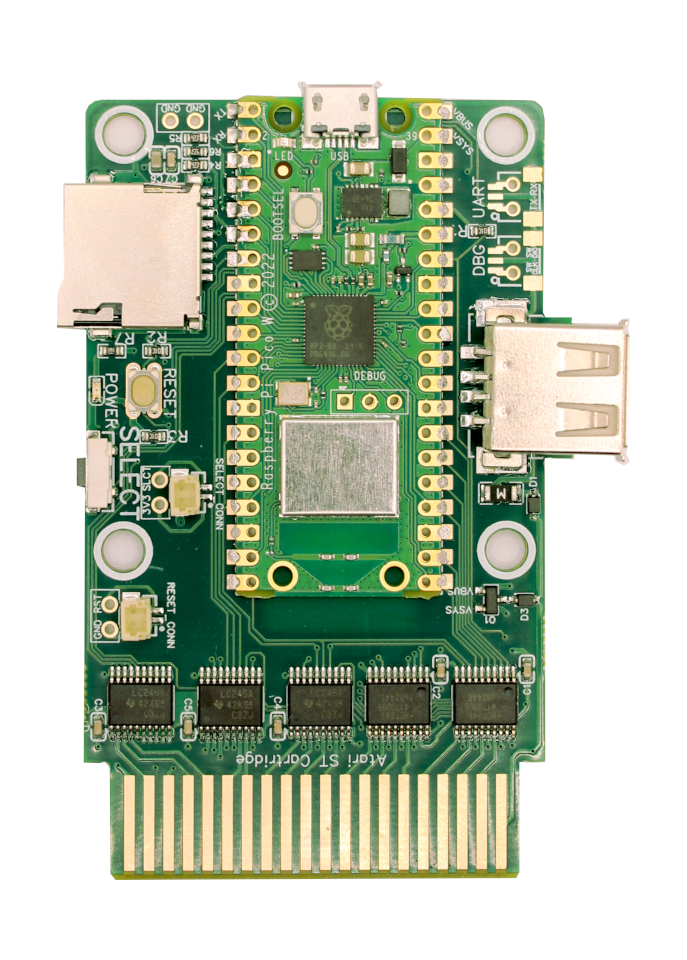
So, I started thinking about a device that could emulate the TOS ROMs using a microcontroller and a program that could load the TOS image and use bit-banging to emulate the ROMs. That was the very first idea of the SidecarTridge TOS emulator, as you can see in the picture.

It was based on the Raspberry Pi Pico and it worked great. With this device, I could test the device on real hardware. In this picture, I am testing on an Atari 1040STFM computer, but I also built connectors for Atari STE computers easily.

It was a tangle of cables and connectors, but it worked. I could test any TOS on real hardware. I had to keep my computers open, but that wasn’t a problem. The real issue was the unreliability of the cable connectors. I had to be very careful when testing the device, but it was perfect for me.

But then I started thinking about the issues I saw in the Atari ST community and other retro-computing communities when they want to use customised firmware for their beloved vintage computers. Or how the adoption of an incredible project like EmuTOS could be easier if they could use it without compromising retro-compatibility with older software.
Can a device like this help the retro communities?
And the answer is… who cares!? 😆 Obviously, I would love to help the retro communities, but the main reason for productising this device was simply to have fun during the journey. I love designing and building things. I love learning new things. I love sharing my knowledge. And I love seeing people use my creations.
That’s all.
SidecarTridge ROM Emulator Development Journey
The Letter to Santa
The new device obviously needed to be an evolution of the first prototype. So, I decided to write a wish list of features I wanted in the new device:
- Maximise the resources available in the RP2040 microcontroller. The RP2040 has 264 KB of RAM. To fully support emulation of ROMs with 256KB of data, the code to emulate the ROMs should be no more than 7KB of RAM plus 1KB of RAM for the stack. The rest of the RAM should be used to store the ROM data. This means I had to code in C and ARM Assembly to optimise the code.
- Emulate the ROMs at the lowest level possible. The original design of the SidecarTridge Multi-Device project emulates the ROMs at the cartridge design level, mimicking the behaviour of a device connected to the cartridge port. Due to the design decisions of the first Atari ST computers, very common signals like the
/OE(Output Enable) or/CE(Chip Enable) are not available in the cartridge port. Instead, the cartridge port has a single signal called/ROM3and/ROM4that is used to enable the ROMs. This time, I wanted to emulate the ROMs at the lowest level, mimicking the behaviour of the ROMs themselves. This means that the device should be able to emulate the signal ROMs/OEand/CE. The ROM Emulator is electronically different to Multi-device. - The Raspberry Pi Pico board has two megabytes of flash memory. Although it might sound like a lot of memory, effectively it is not. It could only fit 7 256KB ROM images. Hence, the Raspberry Pi Pico board was not an option, as we needed 16MB of flash memory—the maximum supported by the RP2040.
- User friendly. The device should be easy to use. The user should be able to upload the ROM images to the device using a USB cable. The device should be recognised as a USB mass storage device, allowing any user to drag and drop the ROM images to the device. The FAT16 subset is the best solution.
- Small footprint. The device should be as small as possible, making it fit inside any computer case. The initial goal was to make it fit inside the Atari 1040STFM case, but I managed to make it fit inside an Oric Atmos case. The device is double-sided at the expense of the cost.
- Adaptability. The device should be adaptable to any computer with a ROM/EPROM/EEPROM socket with an address space up to 18 bits and a data space of 8 or 16 bits. Moreover, there are rumours of a new RP2040 microcontroller with more RAM available. So, the device should address more space in the future. The device has a 20-bit address bus, but two signals are not in use yet.
- Programmable. The device should be programmable. If a user wants to implement their own firmware, they should be able to do it. The device should have connectors for debugging and logging purposes. It has DEBUG and UART connector.
Let’s see how the SidecarTridge ROM Emulator evolved from a simple prototype into a versatile and powerful tool, designed to meet the diverse needs of the retro computing community.
The ROM Emulator Compact Board Prototypes
And this is where the fun begins. I decided to design a board with the following features:
- RP2040 microcontroller
- 16MB of flash memory
- Level shifters to convert from 3.3V to 5V and vice versa
- Bus address and data multiplexers controlled by the RP2040 microcontroller
- USB-C connector
- Dual 5V power supply (USB-C and external) with short-circuit protection
- 5V and 3.3V power lines in the board
- DEBUG and UART connectors
- 20-bit address bus -2 signals not in use yet-
- 16-bit data bus, but 8-bit also supported
/OEand/CEsignals- Optionally more signals
- 40-pin DIP package
I had to iterate through four designs until I got a valid design ready for production.
Second Prototype: Hybrid Design
Before designing a fully functional board, I had to validate some of the design choices. So, I designed a hybrid board where the RP2040 microcontroller was on a custom single-sided board, and the rest of the components were on a custom development board. The main goal of this design was to validate the RP2040 microcontroller and the 16MB of flash memory design. It was my first design from scratch, and I felt the biggest challenge was building my own custom RP2040 board.

It was a success. The RP2040 microcontroller worked as expected, and the 16MB of flash memory let me store 63 256KB ROM images. It also implemented the power line that converts from 5V to 3.3V.
I was ready to design the final board… or so I thought.
Third Prototype: The Big Fail
This was probably my biggest failure in hardware design so far. Since one of my design constraints was to create a board as cheaply as possible, I decided to go with a four-layer single-sided design. However, no matter how much I tried, I couldn’t make it small enough. The board wasn’t too big to fit inside the computer cases, but it wasn’t small enough either.

But not all decisions were wrong. The board worked as expected, and a very important design decision was validated: the concept of a cheap carrier board to fit inside any computer with the ROM emulator board on top as a separate element proved to be a good idea.
Fourth Prototype: Almost There
I decided to design a new board with the same concept as the third prototype but with a different layout. This time, I used a four-layer double-sided design. The main goal was to make the board as small as possible. And I did it. Not as cheap as I wanted, but it was a good compromise.
This is how the board came with the v-cut from the manufacturer:

In this picture, you can see the board and the connectors for the DEBUG and UART:

This design was really good and I’m using it in my own computers, but I still had to make some changes before production. The main change was to add an extra connector for the RESCUE signal. This signal is used to recover the device if a ROM image is corrupted. A problem I found with this prototype was that a happy user might copy multiple ROMs, but if one of the ROMs was corrupted and become the active one, the device wouldn’t work. The user would have to open the device and reprogram the ROMs images again. With the RESCUE signal, the user can recover the device with a functional ROM image without opening it.
I also decided to add two placeholders for the DBG and UART connectors as JST SH connectors, like the Raspberry Pi Pico WH. This way, the user can connect the device using the existing connectors for the Raspberry Pi Debug Probe out of the box.
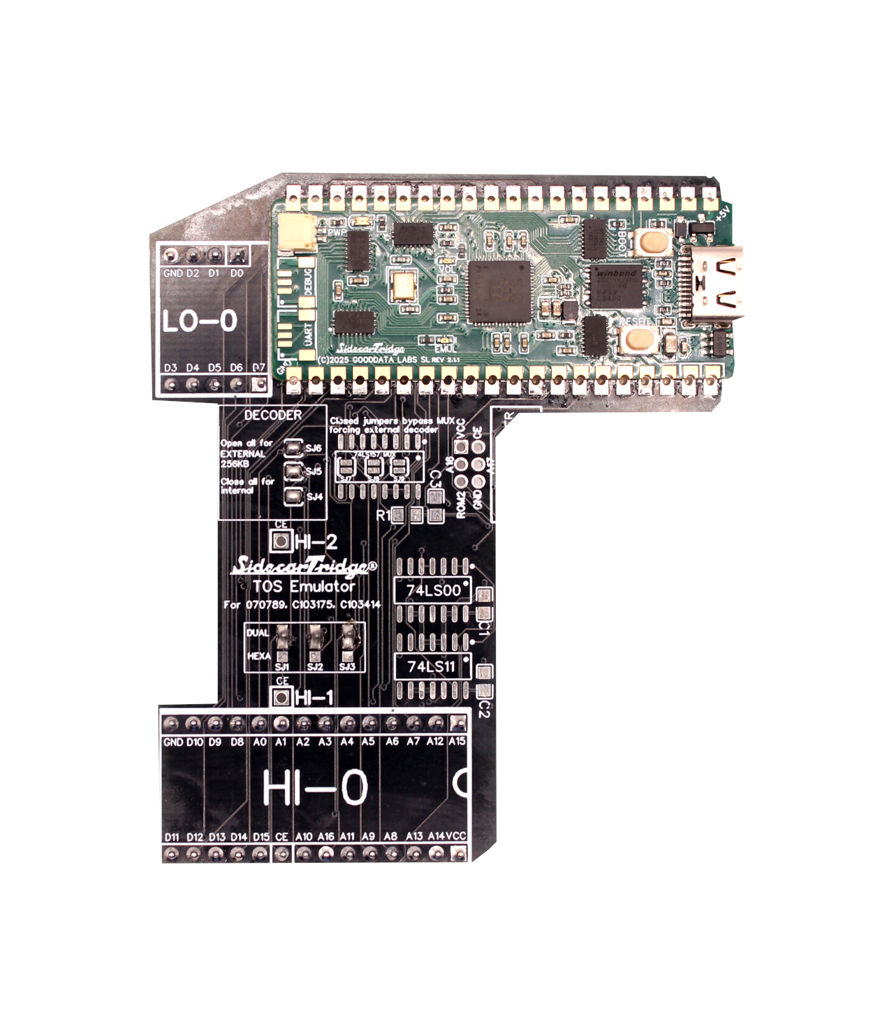
The Final Design
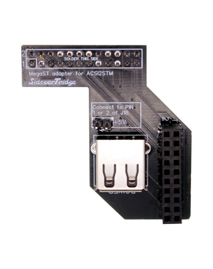
The final design is what you can see on the product page. It is the board soldered on the carrier boards for the Atari STF / STFM / STE and Mega STE. More carrier boards are on the way, also for other computers like Oric and Amiga.


The pinout diagram is also available on the product page:

Software Features: more on the Letter to Santa
The letter to Santa also included a list of software features that I wanted the device to have:
- ROM images upload. The device should be able to store multiple ROM images simply by dragging and dropping the ROM images onto the device. It should be recognised as a USB mass storage device when connected to a PC/Mac/Linux computer.
- ROM images selection. The device should be able to select the ROM image to be used when connected to the PC/Mac/Linux computer.
- ROM images selection on the device. Changing the ROM image from the PC/Mac/Linux computer is nice, but it is not the most common use case. The most common use case is to change the ROM image from the retro computer. So, the ROM emulator should implement some kind of software strategy to select the ROM image from the retro computer.
- The retro computer will not be aware of the ROM emulator. The ROM emulator should be transparent to the retro computer, which should not be aware of the ROM emulator. The ROM emulator should be able to emulate the ROMs as if they were real ROMs.
- Reconfigure the device for different data bus sizes and speeds. The device should be able to emulate ROMs with 8 or 16 bits of data bus and at different speeds.
- Upload new ROM image from the retro computer. The device should be able to upload a new ROM image from the retro computer. This is useful when the user wants to test a new ROM image without needing to open the device.
Mass Storage Device or Emulation Device
As I have explained before, the device has two different modes of operation: mass storage device mode and emulation device mode. Sadly, I found out very soon that both features did not fit in the 7KB of RAM available. So, I had to split the features into two different firmwares. When the device powers on, it checks if the power comes from the USB-C connector. If it does, the device loads a different firmware that implements the mass storage device mode. If it does not, the device continues with the emulation device mode.
Loading a different firmware is not as easy as it sounds. The RP2040 microcontroller has a bootloader that is used to load the firmware from the flash memory. The bootloader is not able to load a different firmware from the flash memory. So, I had to implement a custom bootloader that can load a different firmware from another location in the flash memory.
How to Access the Memory of the Device from the Retro Computer
A very interesting challenge was making the device transparent to the retro computer but also able to access the memory of the ROM emulator. The solution was using an ‘abracadabra’ magic word that allows access to the memory of the device. The magic word is a sequence of bytes that the device is waiting for. When the device receives the magic word, it changes the mode of operation and then it’s ready to accept remote commands to access the memory of the device.
Let’s see in this real example how it works with code:
#define MEMORY_EXCHANGE_SIZE 4096       // 4K

// Memory to store the information about the ROM files
unsigned char *buffer = malloc(MEMORY_EXCHANGE_SIZE);

// Read the ROM configuration from the device
// Without the device, will read only garbage
read_rom_config(buffer);


void read_rom_config(void *memory_exchange)
{
    // Loop for the number of words to read
    for (__uint16_t i = 0; i < MEMORY_EXCHANGE_SIZE; i = i + 2)
    {
        __uint16_t read_word = 0xFFFF;
        while (read_word)
        {
            // Read the value and store it in the memory exchange
            __uint16_t value = send_read_rom_command(i, CMD_ROM_CONFIG_MEMORY_ACCESS);
            __uint16_t value_inverted = send_read_rom_command(i, CMD_ROM_CONFIG_MEMORY_ACCESS_INVERSE);
            *((__uint16_t *)(memory_exchange + i)) = BIG_ENDIAN_TO_LITTLE_ENDIAN_WORD(value);
            read_word = ~(value ^ value_inverted);
        }
    }
}

__uint16_t send_read_rom_command(__uint16_t rom_addr, __uint16_t command)
{
    __uint16_t value = 0;
    __uint32_t rom_address = get_rom_address();
    // Send the MAGIC SEQUENCE to the ROM
    send_magic_sequence(rom_address);

    // Send the read command
    *((volatile __uint16_t *)((__uint32_t)rom_address + command));

    // Send the address to read
    *((volatile __uint16_t *)((__uint32_t)rom_address + rom_addr));

    // Restore
    value = *((volatile __uint16_t *)(rom_address));

    return value;
}

void send_magic_sequence(__uint32_t rom_address)
{
    // Send the MAGIC SEQUENCE to the ROM
    // Simply read the ROM address at the given address of the magic sequence
    for (__uint16_t i = 0; i < sizeof(MAGIC_SEQUENCE) / sizeof(MAGIC_SEQUENCE[0]); i++)
    {
        __uint32_t rom_full_address = (__uint32_t)rom_address + MAGIC_SEQUENCE[i];
        __uint16_t scratch_magic = *((volatile __uint16_t *)(rom_full_address));
    }
}
This code is part of the SWITCHER.TOS application used to change the ROM image from the Atari ST computers. In this code, the Atari ST requests the ROM configuration from the ROM emulator. The ROM emulator waits for the magic sequence to change the mode of operation and then it’s ready to accept remote commands to access the device’s memory. The access to the memory is only 16 bits wide and it also implements a complemented value to check the integrity of the data. After the two commands are sent, the device reads the value and returns it to the Atari ST computer. The Atari ST computer reads the value and checks if the value is correct. If the value is correct, the Atari ST computer continues with the next value. If the value is not correct, the Atari ST computer sends the magic sequence again and the process starts again.
With this code, the retro computer can access the list of available ROM images. Now let’s see how to change the ROM image.
How to Change the ROM Image from the Retro Computer
The process to change the ROM image is very similar to the process to read the ROM configuration. The main difference is that the ROM emulator is waiting for a different command after the magic sequence. Now, instead of passing the address of the ROM configuration, the Atari ST computer passes the index of the ROM image to change. The ROM emulator reads the index and changes the ROM image immediately.
Let’s see an example with code:
void send_change_rom_command_and_hard_reset(__uint16_t rom_index)
{
    __uint32_t rom_address = get_rom_address();
    // Send the MAGIC SEQUENCE to the ROM
    send_magic_sequence(rom_address);

    // Send the read command
    __uint32_t rom_full_address = (__uint32_t)rom_address + CMD_SELECT_ROM;
    __uint16_t scratch_cmd = *((volatile __uint16_t *)(rom_full_address));

    // Send the rom_index to select multipled by 2 (because it's a word address)
    rom_full_address = (__uint32_t)rom_address + rom_index * 2;
    __uint16_t scratch_value = *((volatile __uint16_t *)(rom_full_address));

    // Disable all interrupts, wait some seconds and finally do a hard reset
    ...
}
After sending this command, the ROM emulator changes the ROM image and the Atari ST computer is ready to use the new ROM image. As anyone can imagine, changing the TOS ROM image is a very delicate operation, and a hard reset is needed to make the new ROM image effective.
Product Availability
I am a Product Guy. For years, I believed I was a software developer, but no. I am a Product Guy who builds things based on software.
As a Product Guy, my focus goes beyond just writing code. It’s about understanding the needs of users, identifying market gaps, and creating solutions that truly make a difference. I think about the entire product lifecycle—from concept to delivery and beyond.
My journey began with a PCB and lines of code, but it evolved into something much broader. I realised that creating a successful product isn’t just about the technical details; it’s about applying what I’ve learned in my professional career to my hobby. I have dedicated a lot of time to create a product: not only a piece of hardware with some smart software but also a documentation site, an information website, a channel to communicate with users, a guerrilla marketing plan (because I don’t want to spend money in traditional marketing) and a way to deliver the product to them.
The ROM emulator is now available only under the incarnation of the SidecarTridge TOS Emulator for Atari ST / STF / STFM / STE / MegaSTE computers.
What’s Next?
The ROM emulator is a device that can be adapted to any computer with a ROM/EPROM/EEPROM socket with an address space up to 18 bits (in the future 20 bits) and data space of 8 or 16 bits. So the next step is to design carrier boards for other vintage computers like Oric, Amiga, and others.

I am also anticipating the new RP2040 microcontroller with more RAM available. If this new microcontroller becomes available, I will likely design a new version for more powerful computers and consoles.